The Pick
& Place file is the file that gives the exact position of components on
the board.
This file
is automatically generated by your development CAO software.
This file can be exported as the following formats :
- Excel sheet (.xlsx)
- Data file (.csv)
- Text file sort by separators like semicolon (.txt)
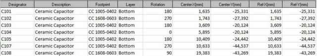
This table contain the following information:
- Designators
- Layer on which the component has to be place
- Absolute placement on the X axis related to the centre of the component
- Absolute placement on the Y axis related to the centre of the component
- Absolute rotation of the component
These five elements above are essentials to create a Pick & Place file, but more information can be add to it as the following ones :
- Component Footprint
- Description of the component
The
absolute position of the component related to the X or the Y axis need to be
define from the center of it to create a correct file, and all mesures need to
be in millimetres in order to be treated later.
The
rotation of the component is unique depending on its origin (library, software
…).
This file
can be upload in the “Files” tab of the EMS Factory website interface.
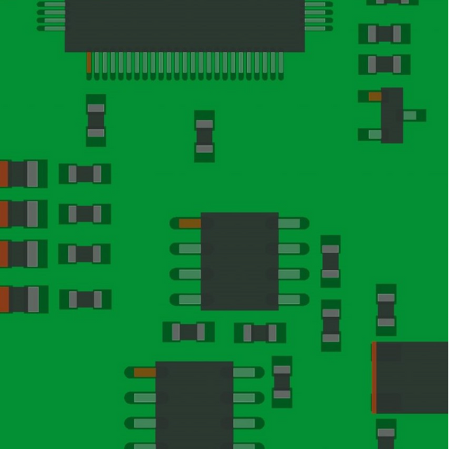
In general
cases, an example of Pick & Place file can be as the following example :
Last articles


Need help ?

FAQ

Resources
